# Modeling with topology primitives
In the introduction we mentioned that all the models in Archiyou are build with the BREP primitives: vertices, edges, wires, faces, shells and solids that are tightly hierarchically connected to each other: An edge is a (specific) sequence of vertices, a wire of edges and so on.
WARNING
If this section is a bit too theoretic for you. Just skip ahead to Constructive Solid Geometry Modeling which is more hands-on. You can always learn about topology primitives later! ☕
# Starting (inifinite) small: Points, Vectors and Vertices
There are no models without points. Most of the time you see them defined as an array [x,y,z] (3D) or [x,y] (2D) but Sketch for example also offers polar coordinates and relative coordinates. At that moment they are just series of coordinates that you can use to make Points, Vectors or Vertices:
vert = vertex(100,0,0);
vec = vector(100,0,0);
pnt = point(100,0,0);
So given that an array like [100,0,0] can be turned into a point, vector and vertex; what is the difference between these three?
- Point: is just that - a 2D/3D point in space - it has very little properties or actions. It's basically a mathematical construct
- Vector: A Vector can be seen as a point with an extra property: magnitude. So where a point is just [100,0,0] a Vector [100,0,0] s seen as the entity between [0,0,0] and [100,0,0], so with a magnitude or length of 100 units. It has also a direction: it points somewhere. Vectors can also be added together, subtracted or normalized. See Wikipedia (opens new window) for a general introduction or Here for a fun one (opens new window)
- Vertex: A Vertex is a point Shape and is thus visible where a Point is not in Archiyou. Vertices (and not Points or Vectors) are the building blocks of a model by combining into Edges, Edges into Wires, Wires into Faces and so on.
Have a look at all the API reference manual for all the properties and methods of Points, Vectors and Vertices.
TIP
Archiyou tries to make it easier working with points, vectors or vertices by transforming when needed so you don't have to care so much about the distinction! Also a given point as [10,20] without the z coordinate defaults to z = 0. You can even write [100] for [100,0,0]!
# Edges
Edges are sequences of Vertices. Most of the time they have 2 Vertices but can have more (with Splines for example). There are multiple types of Edges: Lines, Arcs, Circles and Splines. You can create them like this:
l = line([0,0,0],[100,0,0]); // a straight line edge
print(l.type()); // Output: Edge
print(l.edgeType()); // Output: Line
a = arc([0,0,0],[100,200,0],[200,0,0]); // an arc ~ half a circle
print(a.edgeType()); // Output: Circle (because arcs are pieces of a circle!)
spl = spline([[0,0,0],[100,100,0],[200,0,0],[300,0,0]]);
print(spl.edgeType()); // Output: BSplineCurve
// ==> an elegant curved line spline through 4 points
This doesn't look like much but there is a lot that you can already to with just points and lines! In fact having a strong diagram makes it so much easier to control even the most complicated Shapes in the later stage.
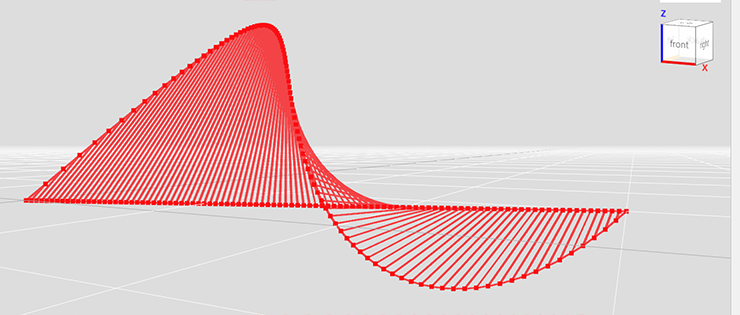
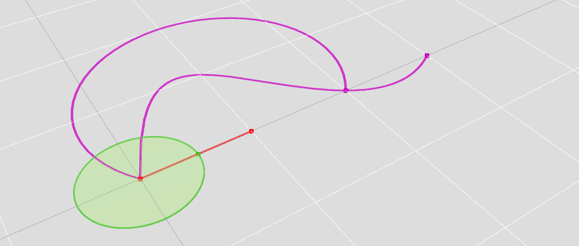
s = spline([[0,0,0],[100,100,100],[200,0,0],[300,100,0]]);
l = line([0,0,0],[300,100,0]);
startPoints = s.populated(50); // generate 50 points on the spline
endPoints = l.populated(50); // generate 50 points on the line

startPoints.forEach( (curPoint,i) => {
        otherPoint = endPoints[i];
        if (!curPoint.equals(otherPoint)) // to avoid zero length Edges at start and end
        {
            line(curPoint, otherPoint); // make a Line between curPoint and otherPoint
        }
    }
);
# Wires
Wires are connecting sequences of Edges. It doesn't matter what type of Edges (Lines, Arcs, Splines etc ); all can be joined into a Wire as long as their start or end Vertices touch each other.
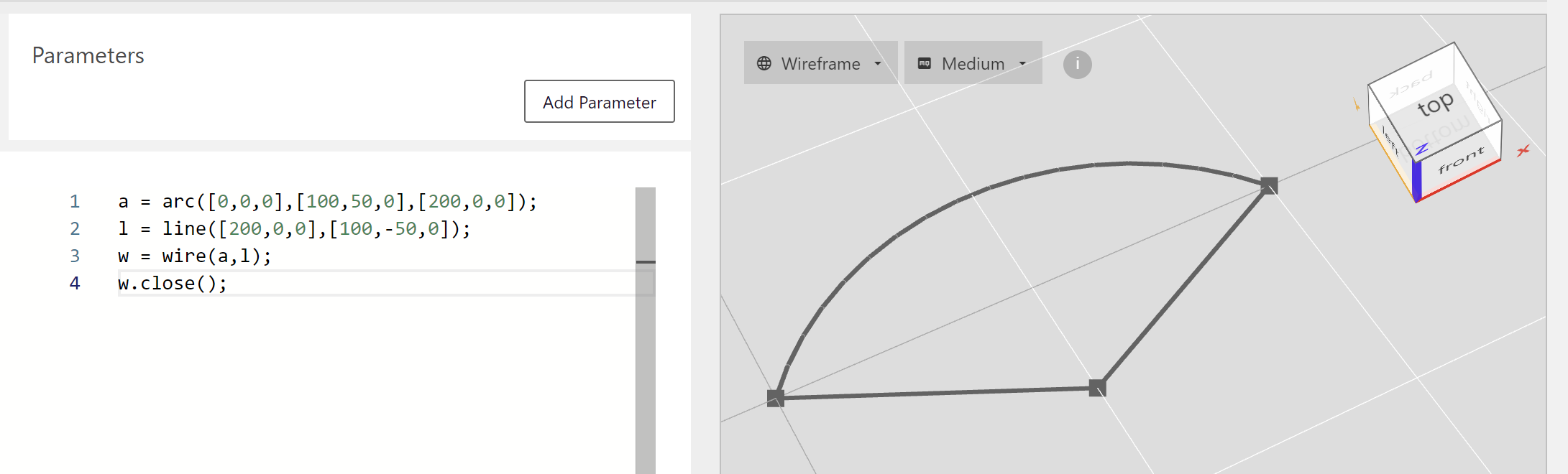
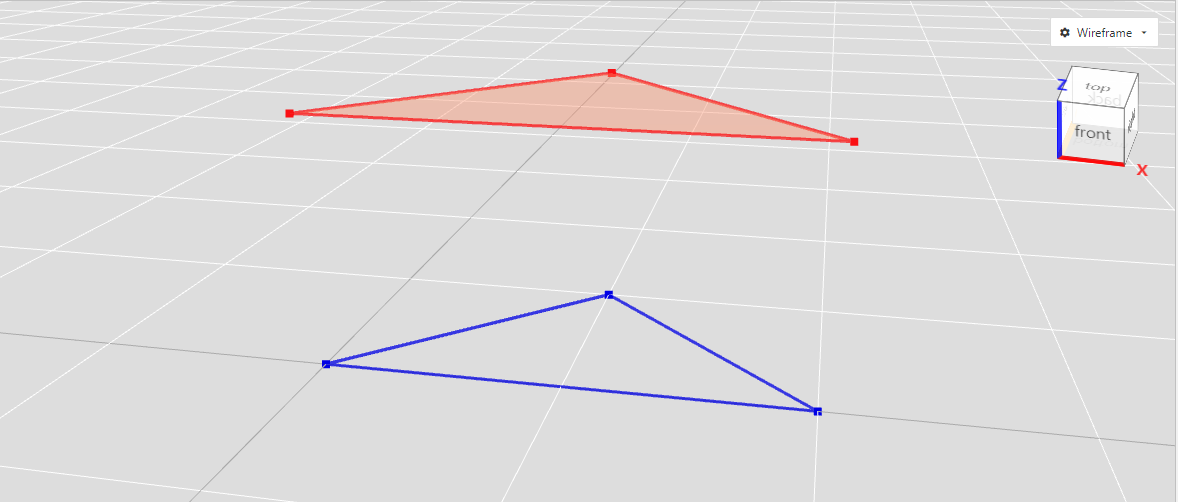
a = arc([0,0,0],[100,50,0],[200,0,0]);
l = line([200,0,0],[100,-50,0]);
w = wire(a,l);
w.close(); // closing the Wire by adding a closing Line Edge to it
TIP
A closed Wire as the above is still just a linear series of Edges. You can convert in to a Face surface with w.toFace(). More information on it below!
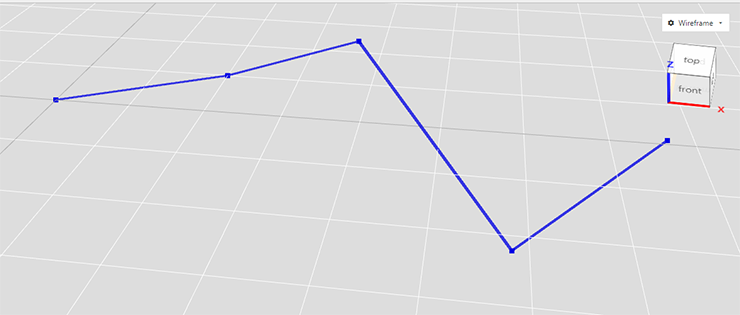
If you want to quickly create a Wire from a sequence of Vertices and connecting them with line Edges:
w = wire(
    [0,0,0],
    [200,100,0],
    [400,0,100],
    [600,-100,-100],
    [800,100,-50]).color('blue');
You can also use combine() (see below) to create Wires from Edges.
TIP
If you are working with models that are based on a lot of 2D lines (Edges and Wires) you probably want to look at the Sketcher!
# Faces
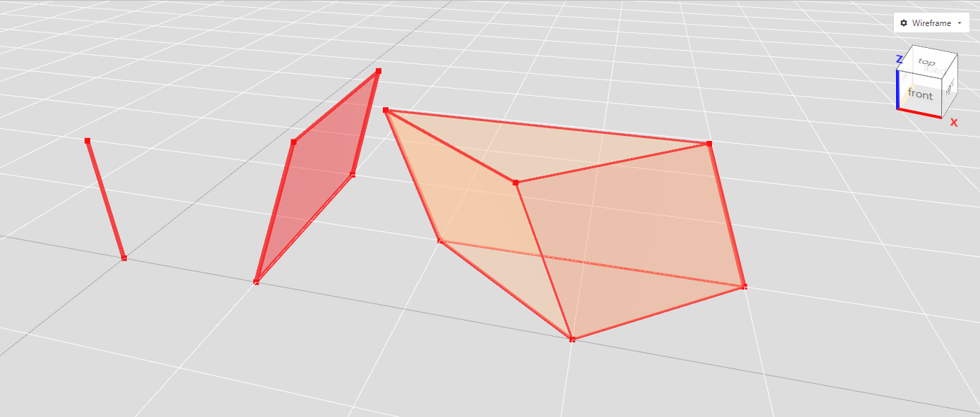
All those Vertices, Edges and Wires are nice, but if you need something more substantial - meaning a model with surfaces or even solid - then you need Faces. A Face is a closed sequence of Edges. So a closed Wire can be converted into a Face without any work.
// create a closed Wire
triangle = wire([0,0,0],[100,100,0],[200,0,0]).close();
triangleFace = triangle.toFace(); // convert that Wire to a Face without any work
triangleFace.move(0,0,100); // move Face a bit up to see it better
As in the image above you can see the difference between a closed Wire and a Face by the fill and of course also in the Scene Navigator [reference to User Guide].
# non planar faces!
Faces in a BREP system can be non-planar (unlike in mesh modeling). This is actually a very powerful feature that we can use in Advanced Surface Modeling.
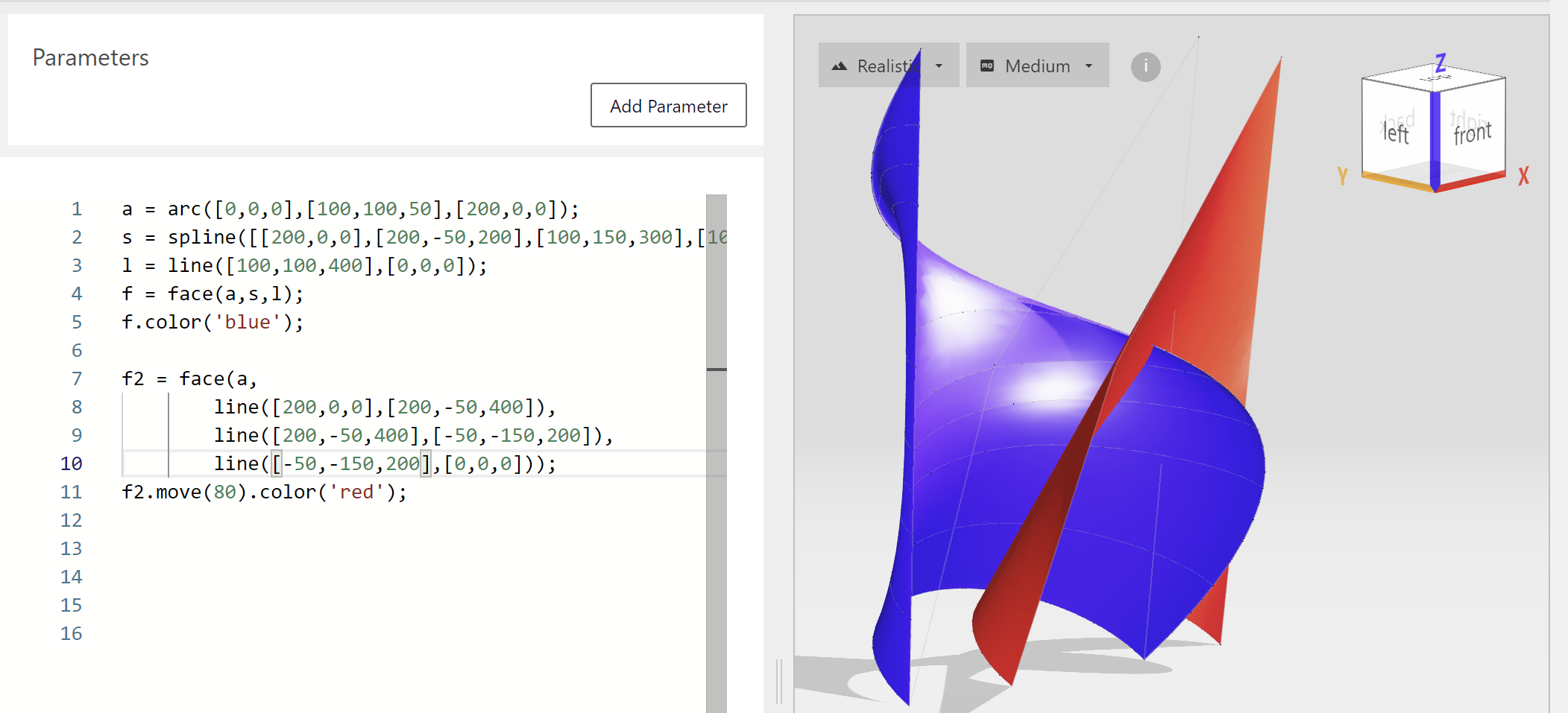
a = arc([0,0,0],[100,100,50],[200,0,0]);
s = spline([[200,0,0],[200,-50,200],[100,150,300],[100,100,400]]);
l = line([100,100,400],[0,0,0]);
sh = face(a,s,l); // it actually becomes a Shell instead of a Face
WARNING
Non-planar Faces can have a maximum of 4 Edges. Planar ones are unlimited!
# Shells and Solids
Continuing on in the hierarchy of topology. A Shell is a connected sequence of Faces and can be created with a list of Edges or Faces. The same goes for a Solid, which consists of one or more Shells that enclose a space. But you would probably notice that creating Shells and Solids out of Vertices, Edges, Wires and Faces becomes rather tedious. That's where operations and later more advanced ways of modeling come in.
# Operations: Extruding, Sweeping, Lofting
# Extruding
With extrude you can create surfaces or solids by 'pushing' profile Shapes (Vertices, Edges, Wires, Faces) along a straight line with a given length. Extruding generates a higher order Shape (Vertex => Edge, Edge => Face, Face => Solid).
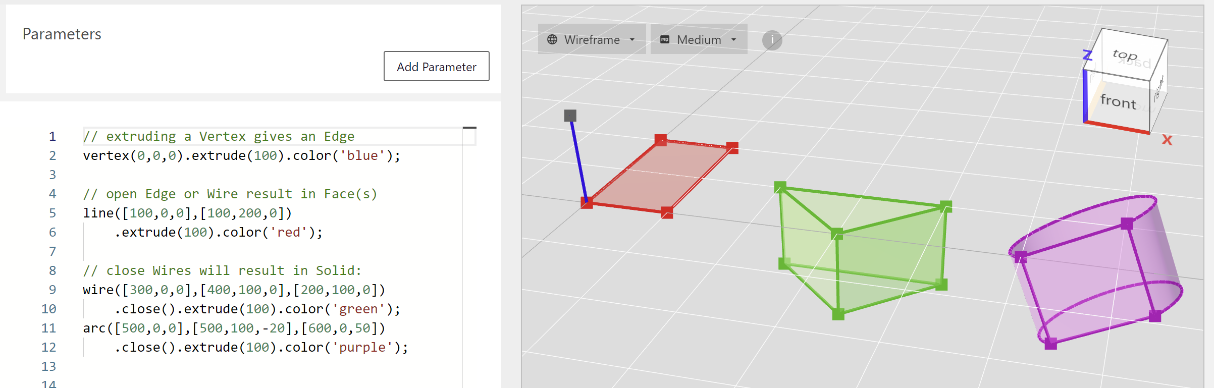
// extruding a Vertex gives an Edge
vertex(0,0,0).extrude(100).color('blue');

// open Edge or Wire result in Face(s)
line([100,0,0],[100,200,0])
    .extrude(100).color('red');

// close Wires will result in Solid:
wire([300,0,0],[400,100,0],[200,100,0])
    .close().extrude(100).color('green');
arc([500,0,0],[500,100,-20],[600,0,50])
    .close().extrude(100).color('purple');
The direction used for extrusion is usually automatically chosen ( based on order of topology, normal of workplane or the z-axis) but can also be given:
vertex(0,0,0).extrude(100,[-1,1,1]); // extrude in direction [-1,1,1]
edge([100,0,0],[100,200,0]).extrude(-100, [0,-1,-1]);
// extrude in direction [0,-1,-1] and the other way (-100)
wire([300,0,0],[400,100,0],[200,100,0])
    .close().extrude(100, [-0.5,0,1]);
If you use minus sign in the extrusion length the direction is reversed.
TIP
Lofting can be done with all Wires and Faces, even the non-planar ones!
# TwistExtrude
Want to make a Shape like a screw thread or a spiral staircase? Shape.twistExtrude() is the method for you:
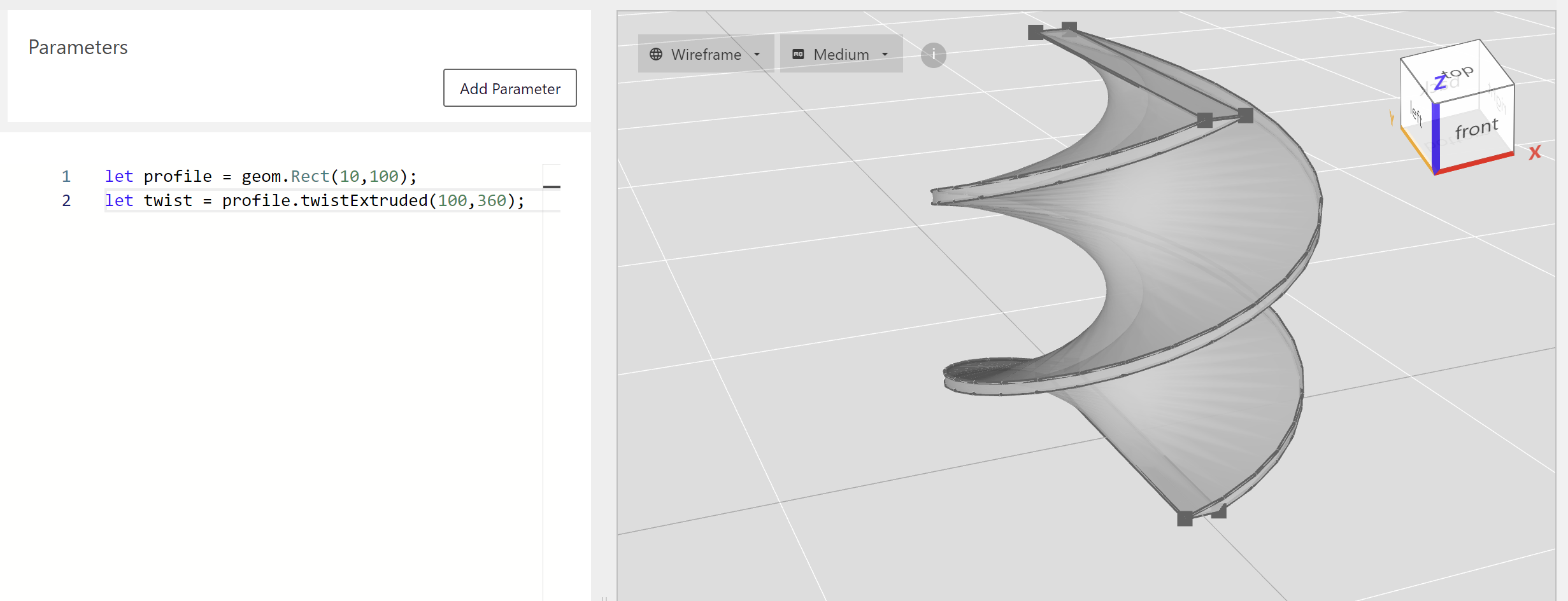
profile = rect(10,100);
twist = profile.twistExtrude(100,360);
You have to be a bit careful though, it can generate rather complicated heavy models.
# Sweeping
Sweeping is extruding along a given Edge or Wire called a spine. An example:
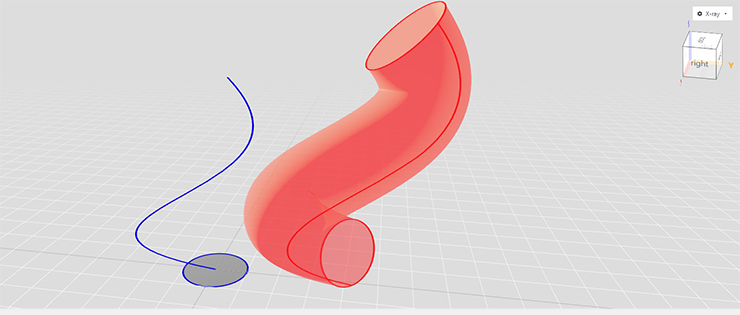
profile = circle(50); // a simple circle
// a spline as the sweep spine
spine = spline([0,0,0],[200,-50,300],[100,150,450],[100,100,600]);
pipe = profile.sweeped(spine);
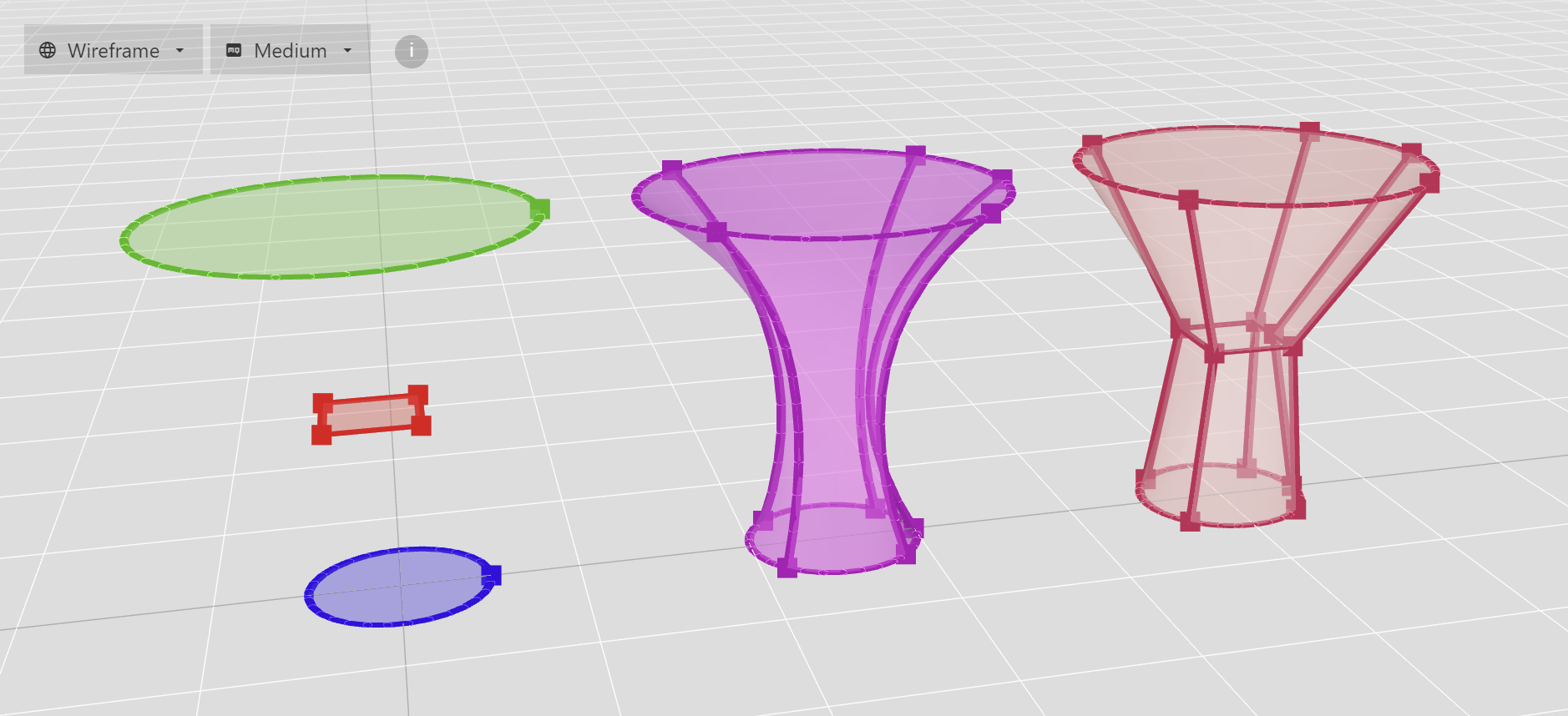
# Lofts
With a loft you can create advanced surfaces or solids by describing them with profiles (basically Vertices, Edges or Wires). The result Shape is a interpolation between these profiles and either a Face, Shell or Solid. Some examples:
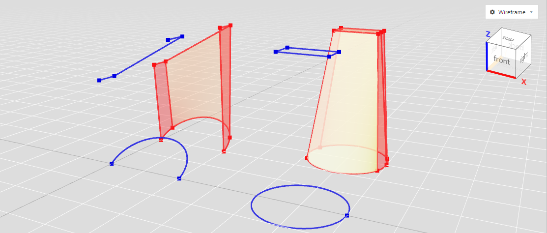
// a surface (Shell) Loft
a = arc([0,0,0],[100,100,50],[200,0,0]);
profile = wire([0,0,200],[0,50,200],[200,50,300],[200,0,300]);
a.lofted(profile).move(0,200,0); // make a loft and move a bit so we can see it

// a solid Loft
c = circle(100).move(400,0,300); // create circle and move a bit out of the way
r = rect(100,50).move(400);
c.lofted(r).move(0,300,0).color('blue'); // create loft and move a bit
TIP
Lofting can be done with all Wires and Faces, even the non-planar ones!
TIP
If given multiple profiles to loft it creates a smooth curved Shape with interpolation. When lofting sequentially with each profile you can get a lineary interpolated Shape.
# Revolving
With revolve you can be create a Solid Shape by rotating a linear Shape (Edge, Wire) along a axis like with a lathe machine. An example:
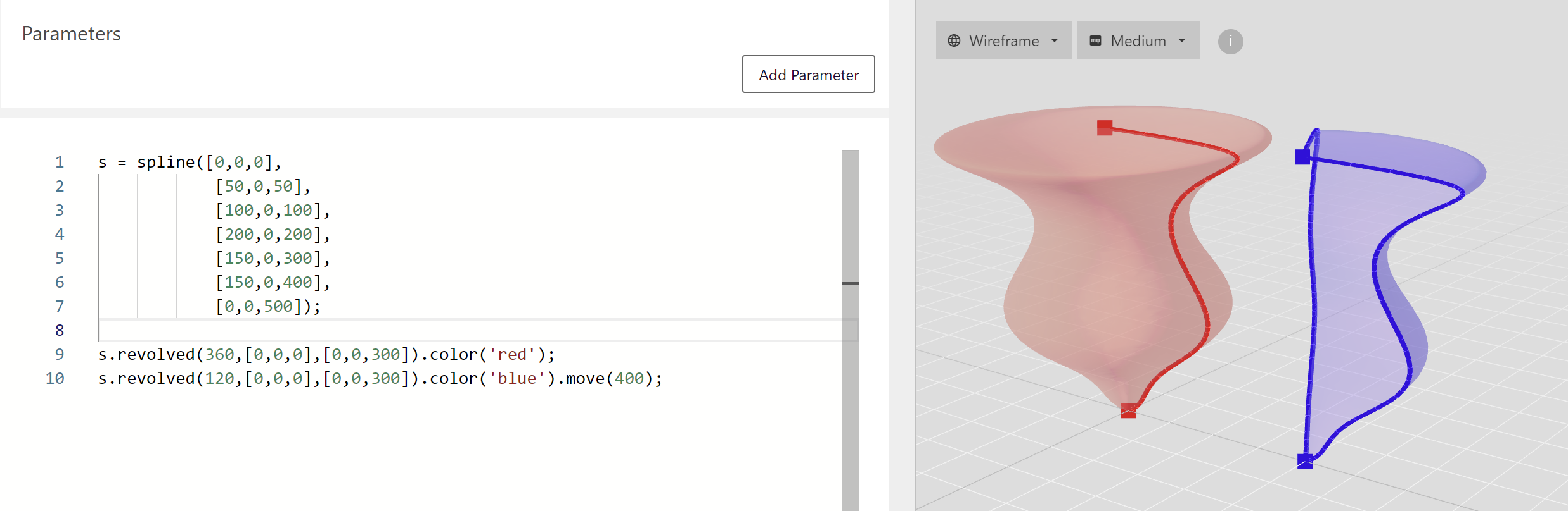
s = spline([0,0,0],
            [50,0,50],
            [100,0,100],
            [200,0,200],
            [150,0,300],
            [150,0,400],
            [0,0,500]);

s.revolved(360,[0,0,0],[0,0,300]).color('red'); // 360 degrees for a closed Solid Shape
s.revolved(120,[0,0,0],[0,0,300]).color('blue').move(400); // less for a segment of it
# Accessing Subshapes
Every Shape except the rudimentary Vertex consists of its topological subshapes. You can always access them:
    box = geom.Box();
    box.vertices(); // 8 vertices
    print(box.vertices()) // console: ShapeCollection< shapes=[...] >
    // A ShapeCollection behaves a lot like an array too!
    box.edges(); // the 12 line edges of the box
    print (box.edges()[0].subType()); // console: Line
    box.wires(); // the 6 closed and coplanar Wires
    print(box.wires().length) // console: 6
    print(box.wires()[0].subType()) // console: CoplanarClosed
    box.faces(); // the 6 faces enclosing the box
    box.shells(); // 1 enclosing shell

    // extract a face from the box as a own Shape and move around
    box.faces()[0].copy().move([0,0,100]);
WARNING
Subshape accessors like vertices() return a ShapeCollection of references to the subshapes; they remain part of the Shape. When you want to extract them and use them to build something else use Shape.copy()
# Selectors
If you need to select specific parts of a Shape with a bit more finesse than subschape accessors Archiyou offers Selectors [TODO: TO REFERENCE]. Especially in combination with advanced operations like fillet and chamfer/bevel they are very powerful. Some examples:
    // Overview of selectors:
    box = geom.Box(100); // box of size 100
    box.select('E|Z'); // 4 Edges parallel to Z-axis
    box.select('E||front'); // 4 Edges that are part of the front Face
    box.select('F||top'); // top Face
    box.select('V@X=-50'); // 4 Vertices with x coordinate of -50
    box.select('E::line'); // all 12 line Edges of the Box
    box.select('V<<->[-100,0,0]'); // 4 Vertices closest to point [-100,0,0]
See Access parts of your model for more information on subshapes and selectors.
# Transforming Shapes
In conventional CAD software it's sometimes a task to find the right way to create something based on something else and you might need to find a certain conversion hid away in some menu. This will break the intuitive design flow although that intuition might be underdefined. Archiyou tries to go along with it and create something anyway that can be iterated upon. Transforming between (collections of) topologies (while maintaining topology validity) is an important part of that:
| Vertex | Edge | Wire | Face | Shell | Solid | |
|---|---|---|---|---|---|---|
| Vertex | - | - | - | - | - | |
| Edge | vertices() populated() | toWire() | - | - | - | |
| Wire | vertices() populated() | edges() segmentized() | toFace() will try close() | toShell() [single Wire Shell] | ||
| Face | vertices() populated() | edges() segmentized() | wires() outherWires() innerWires() | toShell() [single Face Shell] | - | |
| Shell | vertices() populated() | edges() segmentized() | wires() outerWires() innerWires() | faces() | toSolid() will try close() | |
| Solid | vertices() populated() | edges() segmentized() | wires() outerWires() innerWires() | faces() | shells() |
Some methods might come in handy when deep-diving into Shape conversions:
- Shape.checkDowngrade(): AnyShape - If a Shape can be easily downgraded (for example when a Shell only has one Face, or a Wire only one Edge) return downgraded Shape
# Combining Shapes
For now there are limited ways to combining topology Shapes after they are created. Here as some possibilities:
- ShapeCollection.upgrade() : ShapeCollection - Try to create higher order Shapes from given collection. For example by combining connected edges into a Wire:
l = line([-100,0,0],[0,0,0]);
a = arc([0,0,0],[100,100,0],[0,0,200]);
// combine and added to scene
c = collection(l,a).upgraded();
In the future we'll offer more ways to intuitively combine and transform Shapes. Here is an overview:
| collection of | Vertices | Edge(s) | Wire(s) | Face(s) | Shell(s) | Solid(s) |
|---|---|---|---|---|---|---|
| Vertices | collection of Line Edges | Wire with Line Edges | try to close Wire | pointcloud reconstruction (not implemented) | pointcloud reconstruction (not implemented) | |
| Edges | vertices() | combine into one or more Wires planar: OC EdgesToWires() | try to close Wire(s) planar: OC WiresToFaces() | check connected try fill() | check closed try close() | |
| Wires | vertices() | edges() | try to close Wire(s) into Faces | check connected try fill() | check closed try close() | |
| Faces | vertices() | edges() | wires() | check connected try fill() | check closed try close() | |
| Shells | vertices() | edges() | wires() | faces() | check closed try close() | |
| Solids | vertices() | edges() | wires() | faces() | shells() |
Let's quickly move on to Constructive Solid Geometry modeling which is a bit simpler.